I just uploaded to svn.zope.org a new package called z3c.sharding. It is a BTree container that spreads its contents among multiple databases in an automatically balanced way. It does all of its work with pure and simple ZODB mechanisms. It should be useful for solving certain kinds of scaling problems. Enjoy! There are no releases yet, but go ahead and try it out; if it solves a real problem in its current state, I’ll make a release.
Always Run the RelStorage Tests
I would like to advise all users of RelStorage to run the RelStorage test suite on their staging and production servers before running any application that uses RelStorage. There are a number of ways to misconfigure the database and the tests will reveal many kinds of issues. The test suite is in very good shape and should pass every test, every time.
Here are a few MySQL-specific misconfigurations that the tests will reveal:
- An incorrect database adapter. For example, Debian Etch still ships MySQLdb 1.2.1, causing most of the tests to fail.
- Insufficient packet size. In my.cnf, you should increase max_allowed_packet from 16M to at least 32M. This parameter limits the maximum size of an object stored by RelStorage.
- Insufficient space in /tmp. You need a lot more than 16M available, but linux-vserver limits /tmp to 16M by default.
To run the suite, do something like this:
cd /path/to/relstorage

export PYTHONPATH=`pwd`:/path/to/ZODB/src

python relstorage/tests/testmysql.py  # or testpostgresql.py or testoracle.py
Personally, every time I run these tests on a new database, I discover something misconfigured. It is worth the time to run the tests.
Home Grown RepRap Software
After I switched my RepRap to run on g-codes a few weeks ago, I started writing little Python scripts to do various things like lay down a raft, shut the extruder off and move the platform out of the way, extrude in preparation for a build, and send a g-code file to the controller. All of the scripts rely on a common module that sends a series of g-codes to the controller and waits for acknowledgements. The code has grown and become more interesting:
- I optimized the communication by having the host send enough commands to keep the controller’s 128 byte serial buffer full. The host does this by sending commands before an acknowledgement has been received for commands sent earlier. This works surprisingly well and helps the controller handle many commands per second, which is important for drawing short segments.
- I added code that automatically resumes a build where it left off if the controller restarts during the build. I implemented this because my controller spontaneously restarted several times this week in the middle of a build. I implemented this feature by creating a simple, fast machine simulator in the host. To resume a build, the code resets the controller, sends the g-codes necessary to put the machine back in the state recorded by the simulator, then resubmits the commands the controller never acknowledged. This also works surprisingly well.
- I created a g-code runner that can resume any stopped build. I implemented this because yesterday my controller not only spontaneously restarted, it actually lost its firmware in the process! (I then discovered and fixed a loosely connected ground wire which could have been the culprit all along.) Now I can stop a build at any time, turn off the power, disconnect the USB cable, clean the heater, restart the host computer, turn on the power and reconnect, upload a new firmware, run some g-code to test and prime the RepRap, and finally resume printing exactly where I left off. It’s kind of magical to see it actually work.
So now I have worked around the most common ways a print can fail partway through. This should make it much easier to work through problems with large builds. I can even stop a build with ctrl-C, shut everything off, go to bed, and resume the build another day! I definitely need to start doing that. 😉
By the way, I had to make a minor update to the g-code firmware to make it possible to restore all of the machine state: the G92 code needs to notice and use the X, Y, and Z parameters. The fact that no one has yet done this to the firmware in Subversion suggests that none of the other g-code runners can resume a build like mine can. So I guess this code might be useful to the community. Speak up if you’re interested.
Back to Python, Zope, and Plone
I’ve been writing code for the family history department of the Church of Jesus Christ of Latter-day Saints for the last 4+ years. It has been a good experience and I feel like I’ve contributed and learned a lot, but now I have a new opportunity with my family that I shouldn’t pass up. My family business is now doing software consulting! And guess what kind of consulting offers we’re getting? It’s all Python, Zope, and Plone! I’m really happy about that. I feel like working in Python gives us a good chance to advance the state of the art.
Our first full time gig starts in December. It will involve a lot of work with RelStorage, which is another cool bonus. We expect the work to take six months, maybe a little more. Among other work, we are going to make RelStorage rock on MySQL (even more than it does already).
I also need to tie up some loose ends on RelStorage: I need to integrate the optimized Oracle queries, finish setting up the test environment, and release 1.1. (It’s about time, eh? Version 1.1c2 has been out there a long time. Blame Java… 😛 )
Delay Compensation in the G-Code Firmware
I’ve been building small RepRapped objects successfully. (Larger objects not so successfully… I’ll talk about that another time.) One significant problem I’ve noticed is that a series of short line segments is drawn much too slowly. You can see this if you draw a circle using just the cartesian bot. If the circle has only a few segments, then it is drawn at about the speed you specify, but the speed falls as the number of segments increases.
The RepRap host software has several knobs intended to compensate, but I found it very difficult to find the right adjustments. No adjustment seemed to be right for all line segments. The knobs in Skeinforge seem even more complicated.
I tried to compensate for the delays by adding buffers to the G-Code firmware. I figured that if the firmware always has the next command ready in a buffer, there will be no pauses. I wrote code that buffered several line drawing commands in the Arduino, but as it turned out, even a 16 segment buffer did not reduce the pauses at all.
Then I started thinking about what’s really going on. The Arduino can’t calculate anywhere near as fast as a modern CPU. For each line segment, the Arduino does a lot of floating point calculations, including several decimal to floating point conversions and a square root operation to calculate the line distance. No amount of buffering or interrupt coordination is going to reduce the time required to perform those calculations. We could move some of the calculations to the host, but I am not interested in giving up the current simplicity of the protocol.
So then I started to think about compensating for the command processing delay automatically. I realized that every line drawing command is likely to incur about the same amount of calculation delay. All I need to do is raise the feed rate automatically to compensate for the delay.
Using a little algebra, I found a simple way to calculate an adjusted feed rate based on the line distance and a constant command processing delay. I added code to the firmware that performs that calculation, then I wrote a script that computed the delay per line drawing command. I measured the delay to be about 28 milliseconds.
I plugged that number into the firmware and it worked! Now, drawing a curve takes about the same amount of time whether there are 16 segments or 500. I hardly have to worry about beading or stretching anymore.
The adjustment works so well in practice that I don’t think the host needs to be able to control it. It adjusts the speed of every segment, regardless of what host software produced the commands, and not just short segments; it adjusts short segments more than long segments. The adjustment always seems to produce the expected results. I think everyone ought to take advantage of this because it makes the machine much easier to tune.
I’ve posted the patch on SourceForge.
I’ll describe how I derived the calculation.
r = specified feedrate, mm/s
R = adjusted feedrate, mm/s
d = line distance, mm
w = latency (seconds) per command caused by command transmission and processing
t = time to draw the line
r*t = d
t = d/r
The equation for R should have the same time and should include w:
t = w + d/R
We can reasonably assume that the command processing latency is about the same for every line. R will be slightly higher than r, to compensate for w. By substituting t with d/r, we can compute R.
w + d/R – t = 0
w + d/R – d/r = 0
w/d + 1/R – 1/r = 0
-w/d – 1/R + 1/r = 0
1/r – w/d = 1/R
1 / (1/r – w/d) = R
So computing R is not very hard and we can do it right in the firmware. (After all, the firmware already computes a square root to find the distance of each line, so a couple more divisions will make only a trivial difference.) Note that if w = 0 (implying no command processing delay), then the w/d term becomes 0 and R = 1/(1/r), thus R = r. Also note that (1/r – w/d) can be zero, negative, or so small that R is computed as an excessively large feed rate. We need to handle those situations by limiting the adjusted feedrate to the maximum feedrate the steppers can handle.
The firmware actually deals with feed rates in mm/min, so the equation becomes:
60 / (60/r – w/d) = R
This computation is implemented by the patch mentioned above.
G-Codes Rule!
I’ve switched my RepStrap to use G-Codes, since that seems to be the direction the RepRap project is heading. I’m glad I did! The G-Code protocol consists of ASCII text I can read in a terminal, edit with a text editor, and generate with Python. Now I have several Python scripts for doing various things with the machine. Sometimes scripting is much more comfortable than a GUI interface.
OTOH, I’m also glad I started with the SNAP codes, since the code in Subversion that implements the new protocol isn’t stable yet. Specifically:
- At first, the G-Code firmware failed very badly. Some poking around revealed that the microcontroller was resetting on every strtod() call. This turned out to be a bug in Ubuntu 8.04; the solution was to just grab the latest avr-libc package from the 8.10 release and install it with “dpkg -i”.
- At that point, the compiled firmware was just a little too big to fit on the Arduino. I commented out the support for drill cycling (codes 81-83; do we really need those?), then it fit with room to spare.
- The RepRap host interface can generate G-Code scripts, but the scripts contain very long pauses. I discovered that the G4 codes it was generating were supposed to be in units of seconds, but the code was outputting milliseconds instead. I fixed that and now the generator works fine.
Incidentally, I just measured my extruder’s output rate, and this seems like a good place to keep a record. I set the motor speed to 170 (the range is 0-255 and it drives a 10.4V PWM transistor… my old power supply outputs 10.4V instead 12V… I’m thinking of replacing it). It pulled in 100mm of 3mm filament in 261 seconds, outputting 2045mm of filament that fell on the floor.
Based on that measurement, I calculate that the extruder outputs 7.835mm/s (470.1mm per minute); I’m sure it outputs a little less when gravity is not involved. It pulls in 0.383mm/s. Since the output rate is 20.45 times the input rate, while the volume is obviously the same, the output diameter must be 1/sqrt(20.45) = 1/4.522 of the input diameter, so the output is about 0.663mm wide. Again, that’s with extra gravity involved; the real thing will be slightly fatter. I’ve been using 0.7mm width as an estimate and I guess that’s very close to correct.
12 Cents Per Gigabyte
640 GB, 7200 RPM, 32 MB cache, 5 year warranty: $75 ($0.12/GB), free shipping. It’s almost too good to be true.
Still, the best drive for MythTV is Western Digital’s low power series. I’ve been using the 750GB GP model with MythTV for about a year now and it has been silent and completely reliable the whole time. It contains an XFS filesystem, which probably helps quite a bit when recording 6 GB/hr (full HD resolution). The MySQL database that MythTV relies on happens to be on another drive, but I imagine it would be fine to put the database on the same drive.
First RepRap Models
The 3D printer is working and I’ve begun calibrating it. There’s still a lot of tweaking to do, but now I can finally watch the whole process in action!
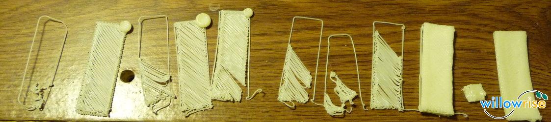
All of these are done with ABS. This is a chronological sequence. On the left, the extruder nozzle was too high above the bed and the ABS didn’t have any desire to stick to the bed. I actually printed half a dozen like this until I made up a sticky bed liner. More on that in a moment…
The second starts to take shape, but there is a big bead of plastic in the top right. It took me several tries to realize why that was happening. Can you guess? It’s kind of funny.
In the Arduino SNAP firmware source code, there’s a constant that defines a stepper motor enable pin for each of the axes. That pin is not mentioned in the wiki, so I figured it had been added since the creation of the wiki page. The enable pin is really useful for saving power. Without the motor enable pin, each axis pulls in 15-20W just to hold its place. That is especially wasteful on the Z axis, which moves very little during a build. I don’t like to waste power, so I connected the motor enable pins to my Arduino.
The firmware source code uses the same pin (15) for all three motor enable outputs. What I didn’t notice is that using the same pin for all three outputs simply can’t work! The RepRap host software prints the first layer, moves the Z axis, then disables the Z motor while it prints the next layer. In my wiring, disabling the Z motor actually disabled all of the stepper motors. D’oh!
I fixed that by disconnecting all the motor enable wires (I imagine there is a pull-up resistor on each board to make the wire optional), then I was finally able to print multiple layers. On the right side of the photo you can see slow progress toward matching the motor speed with the extruder speed. The bar is still very curved; I think the main reason for that is the makeshift sticky bed liner.
My makeshift sticky bed liner is a piece of paper lined with double-stick tape and upside down packing tape. It does stick to the ABS, but it melts and doesn’t stay flat, so the object ends up with a lot of curvature. The bed liner is the next thing to improve.
I do have a Sanguino, which will solve the pin count problem, but I won’t be able to use it effectively until I have a good breakout board for it. Thankfully, Zach is working on that. I could theoretically just solder all the wires, but running 20+ wires off a board with just solder holding them down is asking for trouble. The wires would break too easily.
Let me also talk about what I did with the heater. I said earlier that I would add a metal bar as a sort of strain relief to prevent breakage of the nichrome wire. Here is the heater just before curing the fire cement:
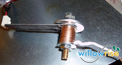
You can see the thin stainless steel bar extending from the brass heater barrel. The bar has a layer of JB Weld for insulation, then the bare copper leads, then another layer of JB Weld to secure the leads. At the end of the bar, the leads curve upward and form a socket, where I have plugged in an ordinary connector. The bar seems to have had the intended effect: even when I get clumsy and bump the heater, the leads are not affected anymore. I wish I had done this from the start–it might have saved me a month of agonizing over broken heaters!
You can see my thermocouple on the right side of the photo. It is covered with teflon tape because previous attempts to build the heater destroyed much of the insulation. I used a thermocouple because I have not found any thermistors designed to handle more than 200 C, and I’ve already determined that extruding ABS reliably requires about 220-240 C. Fortunately, teflon tape can handle 250 C. Here is the heater fully mounted:
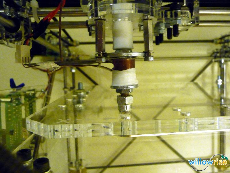
This heater reaches 220C, as measured by the thermocouple, in 5-10 minutes. It is limited to 170C if the cooling fan is turned on. The hottest part of this heater, halfway up the shaft, is about 30C hotter than what the thermocouple measures. If I allow it to get as hot as possible, the thermocouple can reach 240C, but the acrylic securing the heater begins to melt slightly at that point. It does not melt when the thermocouple measures 220C.
I learned that if the heater ever falls below about 185C while ABS is inside the barrel, the extruder will not move forward again even if I bring the temperature back up. I think this is because the small pool of melted plastic just above the barrel cools in a shape that hinders re-melting. When this happens, I can tell that the extruder is still putting enormous pressure on the filament because the drive screw, which usually carves threads into the filament, ends up grinding an almost smooth surface into the filament. To deal with this, all I have to do is re-heat the ABS, run the extruder backwards, and cut off the elongated piece that I pull out. At that point, pushing new filament into the extruder works fine, although the whole process takes 10 minutes or so.
Hasn’t anyone else experienced this? The software ought to provide an option to maintain the heater temperature even when not building. I may just put that in the firmware because the firmware is a lot simpler than the host software.
At the moment, I’m using the firmware and host software released in May 2008, with a few modifications:
- My X axis moves opposite the standard direction. To move to the home position, the stepper needs to step forward, not backward. I had to change the firmware to fix this.
- The temperature measurement calculations simply did not work on the host side. The firmware showed correct measurements while the host thought the heater was freezing at -17C! I dug in and found a hack in the Arduino firmware that makes the measured temperature look like a resistance value so the host software can convert the resistance value back into a temperature. This was apparently done to avoid changing the host software after the conversion from PIC microcontrollers to Arduino. I ripped out that logic from both the firmware and the host software; now the Arduino simply sends the temperature in C (and expects a temperature in C when controlling the heater). All is well. 🙂
As the machine builds, there are a lot of unnecessary pauses that cause the extruded filament to curl. I intend to try out the latest firmware and host software to see if those pauses have been eliminated. I printed out part of the minimug, but there were so many pauses that it was a curly mess.
Anyway, I’m really close now to a fully functioning RepRap!
RepRap Hardware and Electronics BoM
I just posted the detailed bill of materials for the hardware and electronics in my Rep(St)rap. Most of the lines have a comment. The comments and URLs would have made this whole process a lot easier for me, so I hope the spreadsheet helps someone else!
This is the first time I’ve used Google Docs and I must say it’s quite easy to use. I imported from OpenOffice. The conversion of OpenOffice.org formulas failed, but it was fairly easy to sort that out cell-by-cell.
I’m sure some people just want to know what the bottom line was. Well, I paid $555 for the laser cut kit (including shipping), $782 for the hardware and electronics, about $100 for shipping of the hardware and electronics, $100 for 10 pounds of ABS and HDPE spools (including shipping), and $20 for miscellaneous supplies at Ace Hardware. So $1557, and that’s not including the money I spent on new tools (a drill press, 2 vices, a new hack saw, a lot of drill bits, an M6 tap, an M8 die, etc.) and materials I did not use, broke, or forgot to list in the BoM.
Wow, that’s expensive. Buying the complete kit from BitsFromBytes probably would have reduced the price. Still, I prefer this machine and the experience I’ve gained over a big flat panel TV. 🙂
An Abominable, Crazy Idea
What if I were to take a Plone install, delete all of the Zope 2 code (leaving mainly Zope 3 stuff), then mangle the code (including CMF) until Plone works again?
I know I’m foolish for saying this, but my intuition tells me I could actually do it, especially if I got a lot of help from others. I think it would take 1 to 3 months of full time effort. I would redesign all sorts of stuff in the process. The resulting code would not be compatible with any existing site; the necessary migration scripts would take many more months, I think. But the code would be enough to create new sites from scratch and put them on the web. The intent would be to make Plone more maintainable.
It would be really crazy… but fun, I think.