RepStrap Notes for my Past Self

Here are some bits of wisdom I have gained about building and using a Bits From Bytes RepStrap 2.0, in stream-of-thought order.  I wish I had known this stuff before!  I imagine much of this applies to newer machines as well.

  • Essential tools that you may not realize are essential: a small benchtop drill press (AKA pillar drill) if you don’t have a lathe, a good soldering iron (a Hakko 936 is great), solder wick (size #1), a heat gun (Black and Decker makes a good one) and heat shrink, a range of drill bits that differ in size by 1/64″, a bench vice, a good hack saw, a chisel, a metal file, a set of small diamond files, a multimeter with a temperature probe, and a dremel-style tool.  BTW, a drill press is much quieter than a hand-held drill.
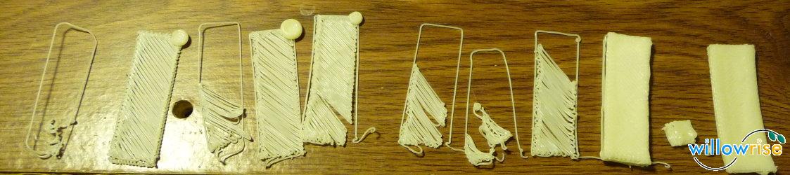
  • As a beginner, buy only PLA.  ABS and HDPE are more difficult because they shrink too much while cooling, pulling the lower layers upward, warping objects with dimensions of about 5 cm or larger.  ABS also smells bad while building.  Warping happens with PLA objects by about 15 cm, but most objects in the community aren’t that big.
  • Warping can break the extruder mount.  Don’t accept warping.  If you break the extruder mount, fix it with super glue and tie the extruder to its mount in more than one place.
  • Loctite Super Glue for All Plastics, #01-07011, works well on acrylic.  Apply it generously and always allow the full 8 hour set time.  If the lid gets filled with glue, drill it out.
  • Loctite Vinyl and Plastic, #01-06998-01, works well for flexible plastic and rubber, such as the Z axis belt.
  • Kapton tape is helpful, although I don’t trust it enough to apply it directly to the nichrome wire on the heater.  I’ve heard that Kapton tape can catch fire.  I use Kapton tape to insulate the copper leads connecting to the nichrome.
  • When building the heater, let the nichrome dangle outside the barrel a bit to avoid breaking the nichrome wire.  The copper/nichrome connection does not need to be inside the heater.
  • Twisting copper and nichrome together, then applying solder, makes a strong bond.
  • Build a 4 ohm heater, not an 8 ohm heater.  A 4 ohm heater can reach the specified temperature more quickly and maintain it better.  The standard transistor can handle 5 amps; a 4 ohm heater at 12 volts consumes only 3 amps.
  • If you short the PWM transistors, they will stay on forever, which could cause a fire.  Use Nophead’s suggested replacement.
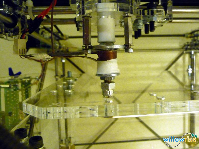
  • Running the object cooling fan continuously (with a PWM setting of 64) seems to prevent jams and burned filament.  To compensate for the fan, add extra cement as insulation and raise the temperature by about 10 degrees.  I used to add fiber glass insulation to the heater, but that made it harder to fix the heater.
  • Ace Hardware sells an 8oz tub of Chimney Sweep Furnace Cement.  I’ve been happy with it.  It cures in minutes with a heat gun. 🙂
  • The copper pipe on the heater seems unnecessary.  I have left it off and I’m happy.
  • Don’t bother with the 30mm washer holding the heater in place.  Cut a piece of thin aluminum instead.
  • The 5V motor can run at 12V, but it’s loud and has a short life (about 2 weeks when I used the machine a lot).  If you use a Solarbiotics DC motor, it *must* be the 12V type.
  • The 12V DC motor, running at full speed, extrudes about 1.6 mm3/s, translating to about 4 or 5 cm3/h, including pauses.  The 5V motor runs faster and can extrude 3 mm3/s.  Too bad it doesn’t work for long.  Trying to extrude more than 3 mm3/s leads to frequent jamming.
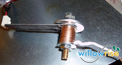
  • The extruder motor has more than enough power.  The much harder problem to solve is gripping the filament; the motor tends to turn the same speed whether grip is achieved or not.  My latest solution for gripping is to sharpen the stainless steel (SS) M8 screw with a diamond file (the drill press is handy for this process) and move the SS washer upward by filing a small slot, so that the washer doesn’t dull the important part of the screw.  This has worked well so far.
  • Make the extruder detachable.  A 9 pin connector is good.  You will remove and improve the extruder dozens (hundreds?) of times before you’re satisfied that it is reliable.
  • Make the heater detachable too.
  • To make a thermocouple, get type K thermocouple wire (with glass insulation) and twist the wires together at the point where you want to measure the temperature.  I don’t think welding the thermocouple is necessary at all.
  • The alarm LED on the thermocouple PCB is very useful.  If it flickers, you probably have broken thermocouple wire.
  • Build on blue painter’s tape (the non-stick side).  I stuck the tape to the acrylic base that came with the BitsFromBytes 2.0 kit.
  • The primary source of wobble is the 608ZZ bearings.  Don’t rely on their accuracy.  I had to change both the Y and Z axes from the standard design so that the bearings could wobble without affecting the machine.  (The X axis might need a similar adjustment.)
  • Some of the acrylic takes too much load and breaks.  I replaced the acrylic piece that connects to the X axis stepper with hacked 1/4″ aluminum.  The fix has been quite reliable.
  • Run the machine from a server so that you can get other work done on your laptop/desktop at the same time.
  • Art of Illusion is very buggy, Blender is just as buggy when performing boolean operations, and OpenSCAD is great once you’ve gone through the slightly difficult process of compiling it.  Use OpenSCAD for anything that requires exactness.  Use Blender for artwork.
  • Both the RepRap host software and Skeinforge are hard to configure correctly.  Many of the defaults are wrong.  Tweaking them takes a lot of time.  Skeinforge is much more flexible.  Get Skeinforge from Subversion and plan to edit the code to fix bugs such as division by zero.
  • Use a G-code firmware, but plan to tweak the firmware.  I hope you can program in both C and Python. 🙂
  • The Oozebane plugin is no good.  In my experience, a much better solution is to add code to the firmware that pauses when starting a segment and temporarily reverses the motor (while the steppers are moving!) after stopping a segment.  The length of the pause depends on how much time has passed since the extruder was last turned off.  A Skeinforge plugin could emulate this behavior, but it’s simpler to do it in the firmware.
  • A new Sanguino board requires you to upload a bootloader, which requires either a programmer or a breadboard and a parallel port.  Most new computers don’t have a parallel port.  I got by with Xubuntu loaded on an old Pentium II that had a parallel port.
  • Both OpenSCAD and Skeinforge often need lots of CPU (2-3 GHz) and RAM (1 GB or more).  OpenSCAD needs a modern 3D video card.  A $30 fanless nVidia card from NewEgg is sufficient.
  • I wrote my own Python scripts for running the machine.  The scripts prepare the machine before starting a build, and can pause and resume a large build.  I’m not sure how others are handling that part.  Maybe I should post my scripts on some server.

Having learned all that and more, I think I am finally ready to build a Mendel. 🙂

Home Grown RepRap Software

After I switched my RepRap to run on g-codes a few weeks ago, I started writing little Python scripts to do various things like lay down a raft, shut the extruder off and move the platform out of the way, extrude in preparation for a build, and send a g-code file to the controller.  All of the scripts rely on a common module that sends a series of g-codes to the controller and waits for acknowledgements.  The code has grown and become more interesting:

  • I optimized the communication by having the host send enough commands to keep the controller’s 128 byte serial buffer full.  The host does this by sending commands before an acknowledgement has been received for commands sent earlier.  This works surprisingly well and helps the controller handle many commands per second, which is important for drawing short segments.
  • I added code that automatically resumes a build where it left off if the controller restarts during the build.  I implemented this because my controller spontaneously restarted several times this week in the middle of a build.  I implemented this feature by creating a simple, fast machine simulator in the host.  To resume a build, the code resets the controller, sends the g-codes necessary to put the machine back in the state recorded by the simulator, then resubmits the commands the controller never acknowledged.  This also works surprisingly well.
  • I created a g-code runner that can resume any stopped build.  I implemented this because yesterday my controller not only spontaneously restarted, it actually lost its firmware in the process!  (I then discovered and fixed a loosely connected ground wire which could have been the culprit all along.)  Now I can stop a build at any time, turn off the power, disconnect the USB cable, clean the heater, restart the host computer, turn on the power and reconnect, upload a new firmware, run some g-code to test and prime the RepRap, and finally resume printing exactly where I left off.  It’s kind of magical to see it actually work.

So now I have worked around the most common ways a print can fail partway through.  This should make it much easier to work through problems with large builds.  I can even stop a build with ctrl-C, shut everything off, go to bed, and resume the build another day!  I definitely need to start doing that. 😉

By the way, I had to make a minor update to the g-code firmware to make it possible to restore all of the machine state: the G92 code needs to notice and use the X, Y, and Z parameters.  The fact that no one has yet done this to the firmware in Subversion suggests that none of the other g-code runners can resume a build like mine can.  So I guess this code might be useful to the community.  Speak up if you’re interested.

Delay Compensation in the G-Code Firmware

I’ve been building small RepRapped objects successfully.  (Larger objects not so successfully… I’ll talk about that another time.)  One significant problem I’ve noticed is that a series of short line segments is drawn much too slowly.  You can see this if you draw a circle using just the cartesian bot.  If the circle has only a few segments, then it is drawn at about the speed you specify, but the speed falls as the number of segments increases.

The RepRap host software has several knobs intended to compensate, but I found it very difficult to find the right adjustments.  No adjustment seemed to be right for all line segments.  The knobs in Skeinforge seem even more complicated.

I tried to compensate for the delays by adding buffers to the G-Code firmware.  I figured that if the firmware always has the next command ready in a buffer, there will be no pauses.  I wrote code that buffered several line drawing commands in the Arduino, but as it turned out, even a 16 segment buffer did not reduce the pauses at all.

Then I started thinking about what’s really going on.  The Arduino can’t calculate anywhere near as fast as a modern CPU.  For each line segment, the Arduino does a lot of floating point calculations, including several decimal to floating point conversions and a square root operation to calculate the line distance.  No amount of buffering or interrupt coordination is going to reduce the time required to perform those calculations.  We could move some of the calculations to the host, but I am not interested in giving up the current simplicity of the protocol.

So then I started to think about compensating for the command processing delay automatically.  I realized that every line drawing command is likely to incur about the same amount of calculation delay.  All I need to do is raise the feed rate automatically to compensate for the delay.

Using a little algebra, I found a simple way to calculate an adjusted feed rate based on the line distance and a constant command processing delay.  I added code to the firmware that performs that calculation, then I wrote a script that computed the delay per line drawing command.  I measured the delay to be about 28 milliseconds.

I plugged that number into the firmware and it worked!  Now, drawing a curve takes about the same amount of time whether there are 16 segments or 500.  I hardly have to worry about beading or stretching anymore.

The adjustment works so well in practice that I don’t think the host needs to be able to control it.  It adjusts the speed of every segment, regardless of what host software produced the commands, and not just short segments; it adjusts short segments more than long segments.  The adjustment always seems to produce the expected results.  I think everyone ought to take advantage of this because it makes the machine much easier to tune.

I’ve posted the patch on SourceForge.

I’ll describe how I derived the calculation.

r = specified feedrate, mm/s
R = adjusted feedrate, mm/s
d = line distance, mm
w = latency (seconds) per command caused by command transmission and processing
t = time to draw the line

r*t = d

t = d/r

The equation for R should have the same time and should include w:

t = w + d/R

We can reasonably assume that the command processing latency is about the same for every line.  R will be slightly higher than r, to compensate for w.  By substituting t with d/r, we can compute R.

w + d/R – t = 0

w + d/R – d/r = 0

w/d + 1/R – 1/r = 0

-w/d – 1/R + 1/r = 0

1/r – w/d = 1/R

1 / (1/r – w/d) = R

So computing R is not very hard and we can do it right in the firmware. (After all, the firmware already computes a square root to find the distance of each line, so a couple more divisions will make only a trivial difference.)  Note that if w = 0 (implying no command processing delay), then the w/d term becomes 0 and R = 1/(1/r), thus R = r.  Also note that (1/r – w/d) can be zero, negative, or so small that R is computed as an excessively large feed rate. We need to handle those situations by limiting the adjusted feedrate to the maximum feedrate the steppers can handle.

The firmware actually deals with feed rates in mm/min, so the equation becomes:

60 / (60/r – w/d) = R

This computation is implemented by the patch mentioned above.

G-Codes Rule!

I’ve switched my RepStrap to use G-Codes, since that seems to be the direction the RepRap project is heading.  I’m glad I did!  The G-Code protocol consists of ASCII text I can read in a terminal, edit with a text editor, and generate with Python.  Now I have several Python scripts for doing various things with the machine.  Sometimes scripting is much more comfortable than a GUI interface.

OTOH, I’m also glad I started with the SNAP codes, since the code in Subversion that implements the new protocol isn’t stable yet.  Specifically:

  • At first, the G-Code firmware failed very badly.  Some poking around revealed that the microcontroller was resetting on every strtod() call.  This turned out to be a bug in Ubuntu 8.04; the solution was to just grab the latest avr-libc package from the 8.10 release and install it with “dpkg -i”.
  • At that point, the compiled firmware was just a little too big to fit on the Arduino.  I commented out the support for drill cycling (codes 81-83; do we really need those?), then it fit with room to spare.
  • The RepRap host interface can generate G-Code scripts, but the scripts contain very long pauses.  I discovered that the G4 codes it was generating were supposed to be in units of seconds, but the code was outputting milliseconds instead.  I fixed that and now the generator works fine.

Incidentally, I just measured my extruder’s output rate, and this seems like a good place to keep a record.  I set the motor speed to 170 (the range is 0-255 and it drives a 10.4V PWM transistor… my old power supply outputs 10.4V instead 12V… I’m thinking of replacing it).  It pulled in 100mm of 3mm filament in 261 seconds, outputting 2045mm of filament that fell on the floor.

Based on that measurement, I calculate that the extruder outputs 7.835mm/s (470.1mm per minute); I’m sure it outputs a little less when gravity is not involved.  It pulls in 0.383mm/s.  Since the output rate is 20.45 times the input rate, while the volume is obviously the same, the output diameter must be 1/sqrt(20.45) = 1/4.522 of the input diameter, so the output is about 0.663mm wide.  Again, that’s with extra gravity involved; the real thing will be slightly fatter.  I’ve been using 0.7mm width as an estimate and I guess that’s very close to correct.

First RepRap Models

The 3D printer is working and I’ve begun calibrating it.  There’s still a lot of tweaking to do, but now I can finally watch the whole process in action!

All of these are done with ABS.  This is a chronological sequence.  On the left, the extruder nozzle was too high above the bed and the ABS didn’t have any desire to stick to the bed.  I actually printed half a dozen like this until I made up a sticky bed liner.  More on that in a moment…

The second starts to take shape, but there is a big bead of plastic in the top right.  It took me several tries to realize why that was happening.  Can you guess?  It’s kind of funny.

In the Arduino SNAP firmware source code, there’s a constant that defines a stepper motor enable pin for each of the axes.  That pin is not mentioned in the wiki, so I figured it had been added since the creation of the wiki page.  The enable pin is really useful for saving power.  Without the motor enable pin, each axis pulls in 15-20W just to hold its place.  That is especially wasteful on the Z axis, which moves very little during a build.  I don’t like to waste power, so I connected the motor enable pins to my Arduino.

The firmware source code uses the same pin (15) for all three motor enable outputs.  What I didn’t notice is that using the same pin for all three outputs simply can’t work!  The RepRap host software prints the first layer, moves the Z axis, then disables the Z motor while it prints the next layer.  In my wiring, disabling the Z motor actually disabled all of the stepper motors.  D’oh!

I fixed that by disconnecting all the motor enable wires (I imagine there is a pull-up resistor on each board to make the wire optional), then I was finally able to print multiple layers.  On the right side of the photo you can see slow progress toward matching the motor speed with the extruder speed.  The bar is still very curved; I think the main reason for that is the makeshift sticky bed liner.

My makeshift sticky bed liner is a piece of paper lined with double-stick tape and upside down packing tape.  It does stick to the ABS, but it melts and doesn’t stay flat, so the object ends up with a lot of curvature.  The bed liner is the next thing to improve.

I do have a Sanguino, which will solve the pin count problem, but I won’t be able to use it effectively until I have a good breakout board for it.  Thankfully, Zach is working on that.  I could theoretically just solder all the wires, but running 20+ wires off a board with just solder holding them down is asking for trouble.  The wires would break too easily.

Let me also talk about what I did with the heater.  I said earlier that I would add a metal bar as a sort of strain relief to prevent breakage of the nichrome wire.  Here is the heater just before curing the fire cement:

You can see the thin stainless steel bar extending from the brass heater barrel.  The bar has a layer of JB Weld for insulation, then the bare copper leads, then another layer of JB Weld to secure the leads.  At the end of the bar, the leads curve upward and form a socket, where I have plugged in an ordinary connector.  The bar seems to have had the intended effect: even when I get clumsy and bump the heater, the leads are not affected anymore.  I wish I had done this from the start–it might have saved me a month of agonizing over broken heaters!

You can see my thermocouple on the right side of the photo.  It is covered with teflon tape because previous attempts to build the heater destroyed much of the insulation.  I used a thermocouple because I have not found any thermistors designed to handle more than 200 C, and I’ve already determined that extruding ABS reliably requires about 220-240 C.  Fortunately, teflon tape can handle 250 C.  Here is the heater fully mounted:

This heater reaches 220C, as measured by the thermocouple, in 5-10 minutes.  It is limited to 170C if the cooling fan is turned on.  The hottest part of this heater, halfway up the shaft, is about 30C hotter than what the thermocouple measures.  If I allow it to get as hot as possible, the thermocouple can reach 240C, but the acrylic securing the heater begins to melt slightly at that point.  It does not melt when the thermocouple measures 220C.

I learned that if the heater ever falls below about 185C while ABS is inside the barrel, the extruder will not move forward again even if I bring the temperature back up.  I think this is because the small pool of melted plastic just above the barrel cools in a shape that hinders re-melting.  When this happens, I can tell that the extruder is still putting enormous pressure on the filament because the drive screw, which usually carves threads into the filament, ends up grinding an almost smooth surface into the filament.  To deal with this, all I have to do is re-heat the ABS, run the extruder backwards, and cut off the elongated piece that I pull out.  At that point, pushing new filament into the extruder works fine, although the whole process takes 10 minutes or so.

Hasn’t anyone else experienced this?  The software ought to provide an option to maintain the heater temperature even when not building.  I may just put that in the firmware because the firmware is a lot simpler than the host software.

At the moment, I’m using the firmware and host software released in May 2008, with a few modifications:

  • My X axis moves opposite the standard direction.  To move to the home position, the stepper needs to step forward, not backward.  I had to change the firmware to fix this.
  • The temperature measurement calculations simply did not work on the host side.  The firmware showed correct measurements while the host thought the heater was freezing at -17C!  I dug in and found a hack in the Arduino firmware that makes the measured temperature look like a resistance value so the host software can convert the resistance value back into a temperature.  This was apparently done to avoid changing the host software after the conversion from PIC microcontrollers to Arduino.  I ripped out that logic from both the firmware and the host software; now the Arduino simply sends the temperature in C (and expects a temperature in C when controlling the heater).  All is well. 🙂

As the machine builds, there are a lot of unnecessary pauses that cause the extruded filament to curl.  I intend to try out the latest firmware and host software to see if those pauses have been eliminated.  I printed out part of the minimug, but there were so many pauses that it was a curly mess.

Anyway, I’m really close now to a fully functioning RepRap!

RepRap Hardware and Electronics BoM

I just posted the detailed bill of materials for the hardware and electronics in my Rep(St)rap.  Most of the lines have a comment.  The comments and URLs would have made this whole process a lot easier for me, so I hope the spreadsheet helps someone else!

This is the first time I’ve used Google Docs and I must say it’s quite easy to use.  I imported from OpenOffice.  The conversion of OpenOffice.org formulas failed, but it was fairly easy to sort that out cell-by-cell.

I’m sure some people just want to know what the bottom line was.  Well, I paid $555 for the laser cut kit (including shipping), $782 for the hardware and electronics, about $100 for shipping of the hardware and electronics, $100 for 10 pounds of ABS and HDPE spools (including shipping), and $20 for miscellaneous supplies at Ace Hardware.  So $1557, and that’s not including the money I spent on new tools (a drill press, 2 vices, a new hack saw, a lot of drill bits, an M6 tap, an M8 die, etc.) and materials I did not use, broke, or forgot to list in the BoM.

Wow, that’s expensive.  Buying the complete kit from BitsFromBytes probably would have reduced the price.  Still, I prefer this machine and the experience I’ve gained over a big flat panel TV. 🙂

There Goes Another Heater Barrel

I put together my fourth heater on Friday and Saturday.  It worked fine for a while; I was able to extrude both HDPE and ABS!  However, after I allowed the plastic to cool in the extruder, I could not get the extruder to drive the plastic again, no matter how hot I melted it.  I had to disassemble the heater to clean it out.  As I was working to remove the ABS, one of the leads attached to the nichrome wire broke.  I don’t have any way to fix those leads, so the fourth heater is lost.  At least I was able to salvage most of the parts.

I now see a pattern in nearly all of the heaters I have built: the nichrome leads have broken every time, and re-heating plastic already in the extruder has never worked and led to major problems.  The re-heated plastic simply refuses to move out the nozzle, no matter how hard the motor pushes; the plastic tends to find alternate paths to exit the heater!

I spent some time thinking about these problems.  I intend to solve the nichrome lead problem by attaching a short metal bar to the heater barrel, the bar extended horizontally, then gluing the leads (bare copper wire) to the bar using JB weld (a hard insulator that can withstand about 310 degrees C).  The extended end of the bar, which should be much cooler than the end attached to the heater, will have a 2 pin socket so I can detach the heater easily.

The problem with re-heated plastic is still a mystery.  The third heater used a PTFE insulator mounted flush against the heater barrel, as specified by the bitsfrombytes diagrams.  With that design, a lot of the plastic exited out the top of the barrel instead of the nozzle, although I can’t remember whether I was using re-heated plastic at the time.  The fourth heater had an 8mm length of the M6 pipe threaded into the PTFE insulator.  Although the fit between the heater and insulator seemed very tight, the ABS still found a way to exit out the top and made a nasty hard shell covering the threads.  I now realize that the M6 tap I used was designed for tapping hard materials like metal, not soft PTFE; an M6 tap designed for soft material would have a slightly smaller diameter.  Next time, I will make my own tap using brass or just force an M6 screw into the PTFE.

By the way, I have begun putting together a BoM for the hardware I actually used.  Tres expressed interest in it and I imagine others will be interested, especially now that Vik has provided a way to buy the laser cut parts for around $400, a lot less than what I paid.  Excellent work, Vik!

My Rep(St)rap

Items of note that you can see in this picture of my Rep(St)rap:

  • I used the BitsFromBytes laser cut plastic with alloy screws and other hardware I bought from McMaster.com and Fastener-Express.com.
  • I decided to mount all of the electronics on a thin 8×10 acrylic plate ($1.58 at Lowe’s) to make power distribution easy and to retain an appearance similar to the rest of the machine.
  • Everything is there but the heater.  I’m still waiting for the nichrome wire to arrive.  I can be patient, so I used free super saver shipping. 🙂
  • I used aluminum gears in place of the plastic ones because the aluminum gears have the same pitch (distance between teeth) as the belts.  Until I did this, the belts slipped a lot, but now it’s actually kind of hard to make them slip.
  • The Z belt tensioner uses an M8 rod instead of an M8 screw.  It extends to the bottom of the cage, giving the tensioner extra stability.

RepRapping

I am a RepRapper!  The RepRap project is an open source effort to build low cost 3D printers.  Yeah, we’re building the seed of a Star Trek replicator.  Don’t expect to eat the results yet, though!

A few months ago I bought the laser cut parts kit from Ian Adkins’ BitsFromBytes store.  I expected that the laser cut kit would be very similar to the standard Darwin design on reprap.org, so I bought just the laser cut parts and ordered the hardware for the standard design from other sources (as listed on the former parts.rrrf.org site, which is now redirecting to Zach Hoeken’s RRRF store).  I hoped to save a little money that way since shipping overseas is expensive.  Unfortunately, the laser cut design is significantly different; in particular, it uses primarily M3 nuts and bolts while the standard design uses M5.  So I ended up ordering a lot of extra hardware.

On the other hand, I don’t think that was such a bad idea, since now I have hard-won knowledge of where to find this obscure hardware.  I know the RepRap project is trying hard to rely on commodity hardware, but metric hardware is rare in hardware stores in the USA, and what they have is overpriced.  So I’ve had to rely on online sources for nearly everything.

In any case, I’ve forged ahead and now my machine is very close to being ready to print.  All 3 axes move smoothly and the extruder motor seems to work well enough.  The only thing I’m stuck on is the heater, which I have tried to build 3 times now, each time making some critical mistake.  I’ve ordered a roll of 30 AWG nichrome wire from Amazon and a brass tube from onlinemetals.com; once they get here, I should be ready to build the heater correctly. I only wish I could buy such things locally so I wouldn’t have to wait!